Meifford Hill


The Chapel and Houses


loco page header

Populating the Hill


The high ground, just outside of Meifford, always referred to as 'The Hill', remained an undeveloped part of the layout for quite some time.

The reason for the hill was two-fold :

  1. It provided a cutting, which disguises the quite steep incline and tight curve to the upper level, whilst giving a backdrop to the line down to the canal.
  2. It was a convenient way to seperate Meifford Town from the canal in addition to providing some interest.

 I always had in my mind an idea of how it would look. To see if it would work I cut out some card shapes, to get the size and positioning right for the buildings and for where the footbridge, providing a link across the track, would actually fit.

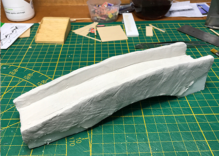
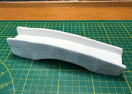
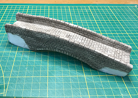
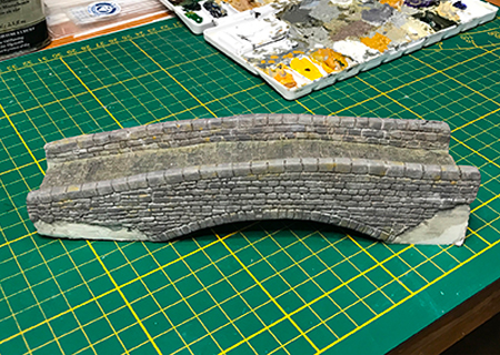
Making the bridge - click on the image below for more information

The clearance under the bridge was critical for placement and design, particularly due to the steep incline. The vertical boiler loco has a particularly tall chimney, so was used to measure this.

Once I was sure of the sizes, then construction of the houses, plus the chapel, was started. I decided that for consistency it was better to construct them all at the same time - it was certainly challenging, particularly the 31 windows that were needed (not including the chapel).

The building nearest the town and low on the hill also had to be removable as it also hides a surface mounted servo, so access for maintenance is essential. This building therefore is designed to 'plug in' to a socket in the ground, which disguises the base and provides a secure fitting.

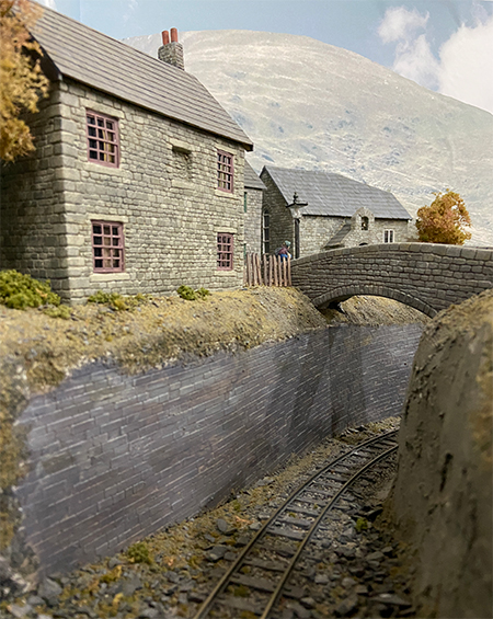
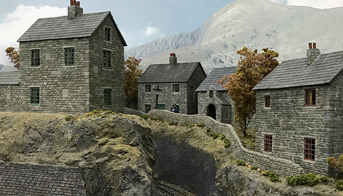
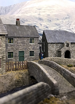
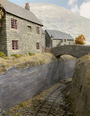
A few views of the hill area -


Click on any image to enlarge

Contact

If you have any questions about Meifford or would like to know more about 7mm Narrow Gauge modelling, please do use the form on the Contact Page


 I normally try and answer within a couple of days

Making the Bridge


I thought that it might be useful to show how I made the footbridge over the cutting. It uses pretty much the same techniques that I employ for the buildings!

It might seem strange, but the base structure is made from 5mm foam board. It was strong enough, but easy to cut and shape to match the sides of the cutting and the 'slot' that had been prepared for it. The whole thing was then given a coat of DAS clay, about 1mm - 2mm in depth, as per the following image -

 bridge 01

Once dry, everything was given a light sanding just to even up the surface a little. Then starting with the capping stones and those forming the arch, the surface was scribed in the usual way. The bridge path was scribed to represent a cobbles, or stone setts.

Eventually it ends up looking like this -

bridge 02

The missing areas of DAS are where the bridge slots into the landscape!

The next step is to give the stone course a very thin dark wash of oil paint plus 90% thinners. The expectation is that the bridge would be pretty grubby after being in place for years, so it represents the dirt that would have collected!

Following that, it will look something like the following. You can begin to see how it will finally look.

bridge 03

 The real work starts after this. I use a palette of about 5 or 6 mixed colours and using a small flat brush colour in individual stones in a random order! I usually leave it to dry for several hours and then use a wider brush, dampened with linseed oil, to blend the colours to get that natural look. For the pathway I also dry-brushed in some green to represent moss, mildew etc. on the surface.

Eventually you get to something like this -

bridge 04

This one is all ready to plant into position. I created a socket for the bridge to slot into on either side of the cutting, with the small joint being disguised with some 'earth mixture' or greenery!

This one show the bridge located in place. As you can see, the cutting is both quite narrow and steep. All the locos manage it quite well, although a train of full slate wagons certainly slows things down a bit!

bridge view